QuEST: Activities
B92 Protocol
In 1992, Charles Bennett proposed the B92 protocol in his paper "Quantum cryptography using any two non-orthogonal states". B92 protocol is a modified version of the BB84 protocol with the key difference between the two being that while BB84 protocol uses four different polarization states of photon, the B92 protocol uses two (one from the rectilinear basis, conventionally H-polarization state and one from the diagonal basis, conventionally +45° - polarization state). The B92 protocol can be summarized in the following steps-
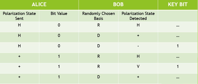
- Alice sends a string of photons in either H-polarisation state or +45° - polarisation state, chosen randomly. H-state will correspond to the bit ‘0’ whereas +45°-state will correspond to the bit ‘1’.
- Bob randomly choses between rectilinear and diagonal basis, to measure the polarisation of the received photon.
- If Bob is measuring in the rectilinear basis, there are two possible circumstances: if the incident photon is H-polarized, then the measurement outcome will be H-state with probability 1 whereas if the incident photon is +45°-polarised, then the measurement outcome will be either H-state or V-state with probability 0.5. Thus, if only the outcome is V-state, Bob can infer confidently that the incident polarization state of the photon is ‘+45°’.
- Similar argument will be applicable if Bob is measuring in the diagonal basis, where the measurement outcome of -45°-state will indicate that the incident polarisation state of the photon is ‘H’.
- After the transmission of the string of photons, Bob announces the instances in which the measurement outcome was either ‘V’ or ‘-45°’ and the rest are discarded by both of them. These results can be used to generate a random bit string between Alice and Bob.
- For the verification of eavesdropping, Bob and Alice publicly share a part of the generated random bit string and if the error crosses a tolerable limit, the protocol is aborted. If not, they now have been able to generate a secure and symmetric key between them.
Another important contrast to the BB84 protocol is that Bob do not have to announce the choice of basis in the post-transmission communication i.e. sifting is not required. The following table shows different possible instances of transmission and measurement results:
Experimental demonstration of the B92 protocol
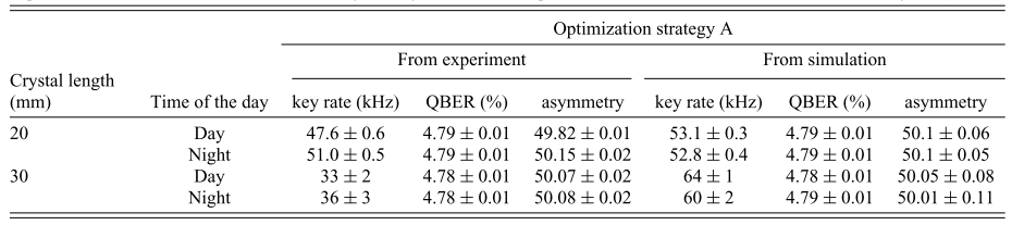
Results
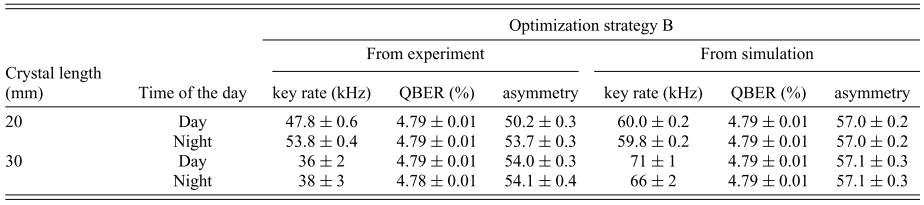
With a transmission channel length of ~2 metres, pump power of 30 mW, and crystal lengths of 20/30 mm, we obtained the following experimental and simulation results:
References:
- R. Chatterjee, K. Joarder, S. Chatterjee, B. C. Sanders and U. Sinha, "qkdSim: An experimenter's simulation toolkit for QKD with imperfections, and its performance analysis with a demonstration of the B92 protocol using heralded photons", Phys. Rev. Applied 14, 024036 (2020).
- R. Chatterjee, S. Chatterjee, B. C. Sanders, and U. Sinha, "An experimenter's toolkit for simulating quantum key distribution protocol implementations", Indian Patent Application No. 202141023697 (2021).
BBM92 protocol implementation over an atmospheric channel
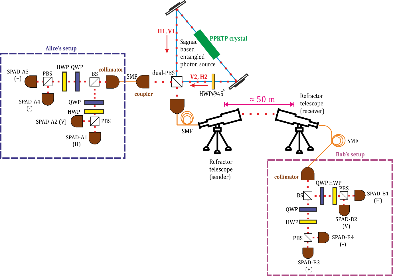
In our BBM92 protocol implementation using polarization-entangled photon pairs that produces an entangled state: |ψ-⟩ = 1/2 { |H1⟩ |V2⟩ - |H1⟩ |V2⟩ },
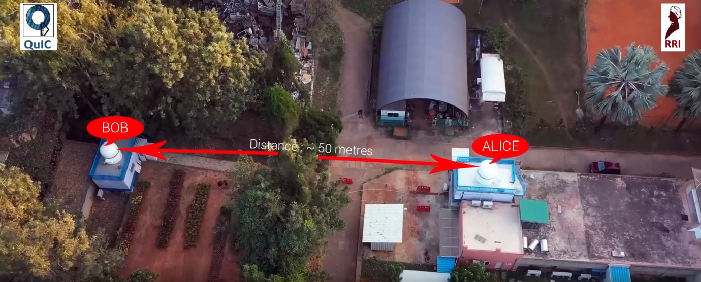
Alice (1) and Bob (2) both measure the stream of incoming photons: say, horizontally polarized i.e. H and vertically polarized i.e. V (or say, V and H). The photons entering the Alice’s and Bob’s setups are segregated randomly, for measurement along the two rectilinear or diagonal projection bases, with a 50:50 probabilities by a beam-splitter. The schematic of our experimental setup is presented in the figure below. The free-space (atmospheric) channel length from sender (source/Alice’s setup) to the receiver (Bob’s setup) is ≅50 meters. Each of these basis projections can again lead to either of the two outcomes (i.e., detection of the photon along the transmitted arm: horizontally (H) or diagonally (D/+) polarized photon, or along the reflected arm: vertically (V) or anti-diagonally (A) polarized photon of the polarizing beam-splitter). Hence, we end up with an overall eight coincidence detections between the Alice’s and Bob’s detector clicks. Out of them four (i.e., A1-B2, A2-B1, A3-B4, and A4-B3) form the desirable set (signal: HV/VH, DA/AD) and the other four (i.e., A1-B1, A2-B2, A3-B3, and A4-B4) form the undesirable set (noise: HH/VV, DD/AA). We assess the number of coincidences in these sets by analyzing the signal-to-noise ratios (SNRs), through the consideration of suitable window spans around the peak maxima. The signal and the noise coincidence values thus obtained within these window regions are then used to compute the raw key rate, the quantum-bit-error-rate (QBER) and the key symmetry of our protocol implementation. Our first measurements in February 2021, achieved a reasonably good key rate along with an information-theoretically secure QBER. This was India’s first demonstration of QKD over an atmospheric free-space channel. This is a part of India’s first project on satellite based quantum communications “Quantum Experiments with Satellite Technology” which is a collaboration between the Quantum Information and Computing lab at RRI and the Indian Space Research Organization.
References:- S. Chatterjee, K. Goswami, R. Chatterjee, and U.Sinha,"Polarization bases compensation towards advantages in satellite-based QKD without active feedback",Communications Physics volume 6, Article number: 116 (2023).
- S. R. Behera, M. George and U. Sinha, "Daytime and Nighttime QKD over an atmospheric free space channel with passive polarisation bases compensation", arXiv:2310.02115.